A foundation drawing for a high mast lighting pole cannot be safely copied from a different project. Even when two masts have the same nominal height, their headframe area, luminaire mass, wind exposure and soil conditions may be different. This guide is for procurement and coordination, not a substitute for a licensed structural or geotechnical engineer.
The soil report comes first
The project engineer needs site-specific geotechnical information such as allowable bearing or resistance parameters, groundwater conditions, settlement considerations and any relevant lateral soil response. A foundation selected for dense ground may be unsuitable for weak fill or a coastal reclaimed site. Ask whether the foundation is designed as a spread footing, pile-supported structure or another approved arrangement. The pole supplier can provide interface loads, but should not invent site soil capacity.
What wind and equipment data change the foundation?
The pole shaft, brackets, headframe, floodlights, access ladder and platform all contribute mass and exposed area. Request the project design wind criteria, terrain/exposure assumptions, applicable code, headframe geometry and complete luminaire arrangement. The designer must assess overturning, shear, uplift, fatigue where relevant and serviceability. Changing from a compact headframe to a larger multi-tier frame can invalidate an earlier foundation concept.
Coordinate the flange and anchor-bolt cage
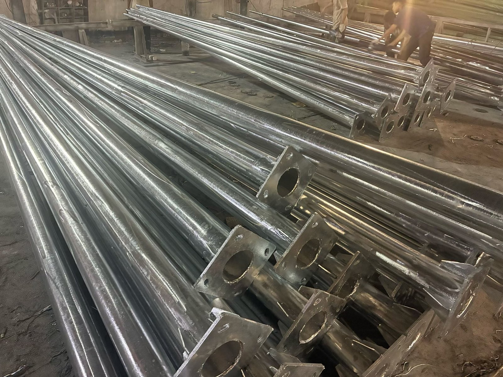
The bolt circle, number and grade of anchors, bolt projection, embedment, washers, nuts and setting template must agree with the approved base plate. Hole diameter and plate thickness are not stand-alone purchasing choices. The anchor cage must clear reinforcing steel and conduit penetrations. A template is useful during concrete placement, but the foundation contractor must verify bolt position and verticality before the concrete sets.
Include cable entry and grounding early
Reserve space for power conduits, pull boxes, grounding conductors and inspection access before reinforcing details are frozen. Confirm whether the pole base has an internal cable opening and how water will be managed. Electrical grounding and lightning protection should follow the site electrical design; an anchor bolt alone is not automatically an adequate grounding system.
Hold points before shipment
A practical approval sequence is: preliminary pole arrangement; supplier reaction loads; geotechnical and foundation engineering; approved anchor layout; final pole fabrication drawings; and installation inspection. If the customer changes pole height, number of floodlights or headframe, request a formal design review rather than silently reusing the original bolt schedule.
RFQ Checklist for EPC Buyers
- Site geotechnical report and groundwater notes
- Design wind criteria and applicable structural code
- Pole shaft drawing and headframe dimensions
- Luminaire quantity, weight, bracket projection and access accessories
- Base flange and anchor bolt interface drawing
- Conduit, earthing and inspection access details
- Engineer-approved foundation and anchor installation drawings
Frequently Asked Questions
Can the manufacturer supply a universal foundation drawing?
A typical detail may help with budgeting, but final dimensions require site loads and geotechnical design.
Can I change from eight anchors to sixteen anchors?
Not without coordinated structural redesign of the flange, anchor group and foundation.
Who signs off the foundation?
The responsible project engineer and local authority where required, not the lighting supplier alone.
Request a Project-Specific SUNLUX Quotation
Share the drawings, project location, quantities, installation constraints and BOQ with SUNLUX Lighting. Our team can review manufacturing and integration requirements and prepare a quotation based on the confirmed scope. Email sales@sunluxledlighting.com or WhatsApp +8619189782897.
Related reading: High Mast Components · Base Flange and Anchor Bolts.