When a roadway contractor asks for a 10 m pole with a 1.5 m arm, the arm dimension is not enough to define the lighting geometry. Pole setback, road width, mounting height, tilt and photometric distribution together determine where light reaches the pavement. This article separates the structural drawing from the lighting layout so buyers can avoid mismatched quotations.
Define outreach from the correct reference point
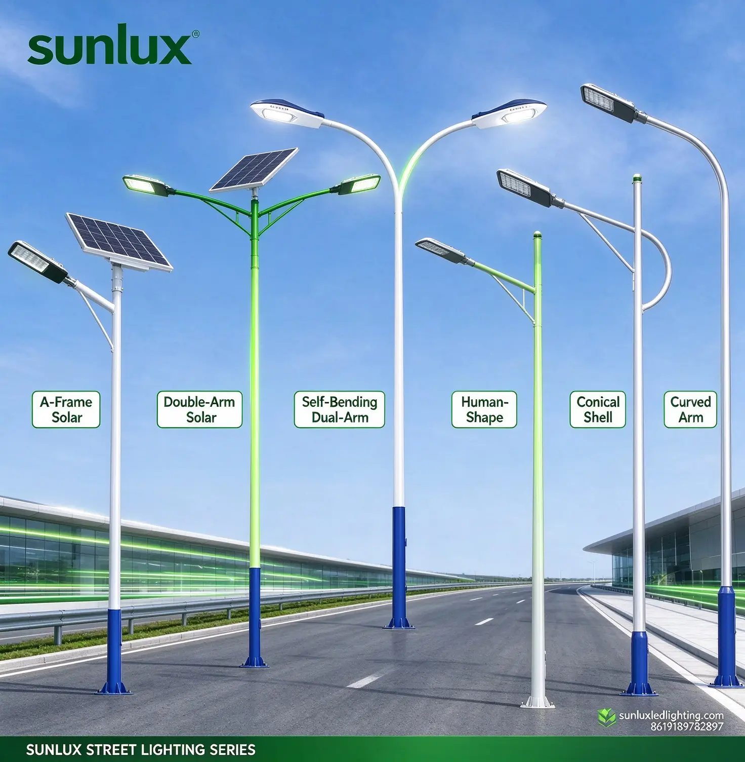
An arm may be measured from the shaft centerline, shaft face or another reference in a project drawing. Clarify whether the dimension is horizontal projection or curved-arm length. Also specify the luminaire mounting spigot, tilt and orientation. Two visually similar arms can place the LED fixture at different coordinates and create different bending moments.
Setback and mounting height work together
Setback is the pole’s distance from a defined road edge or curb reference. Mounting height is usually the luminaire’s optical mounting position, not necessarily the pole’s overall steel height. The designer must coordinate these values with road width, sidewalks, shoulders, obstructions and safe maintenance access. Avoid moving poles toward traffic just to shorten the arm without a roadside safety review.
Choose the layout before fixing the arm
Common road lighting arrangements include one-sided, opposite, staggered and median installations. The FHWA handbook discusses these patterns and emphasizes that spacing and mounting height must be verified by lighting calculations. A central-median double-arm pole can serve both carriageways, but it may require different outreach and optics than a one-sided installation.
Photometric distribution matters more than appearance
An LED luminaire’s IES or LDT photometric file should be used to model average light level, uniformity, glare and spill light for the project. The right arm length is not simply the longest available option. A different optical distribution may achieve the design target with less outreach, but the complete arrangement must be simulated.
Coordinate foundation and installation clearances
Arm projection changes structural loads and may create conflicts with overhead utilities, trees and signage. The approved pole drawing should show arm elevation, luminaire interface, access door orientation and base flange. The installer should check these details against the civil layout before concrete works begin.
Project RFQ Checklist
- Road cross-section, width and lane arrangement
- Pole centerline and setback reference
- Optical mounting height and arm horizontal projection
- Luminaire IES/LDT file and tilt angle
- One-sided, staggered, opposite or median layout
- Clearances to signs, trees and utilities
- Structural drawing and foundation interface
FAQ
Is pole height the same as mounting height?
Not always. Confirm the luminaire optical height on the project drawing.
Is a 1.5 m outreach suitable for every 10 m pole?
No. Road geometry, optics and structural loading must be checked.
Can a double-arm pole reduce pole count?
In some median layouts it may, but total cost and maintenance access need evaluation.
Technical background: FHWA roadway lighting guidance. Apply the standards and approval procedures required by your project jurisdiction.
Send Your Drawings to SUNLUX
For a project-specific technical review and quotation, send your location, drawings, BOQ, quantities and operating requirements to sales@sunluxledlighting.com or WhatsApp +8619189782897. SUNLUX Lighting supports customized lighting products and steel pole manufacturing for B2B buyers.
Related guides: Six Street Pole Designs · 12 m Double-Arm Pole BOQ.